Mercedes OM602 Diesel Engine: Variants, Specs & Failure Analysis
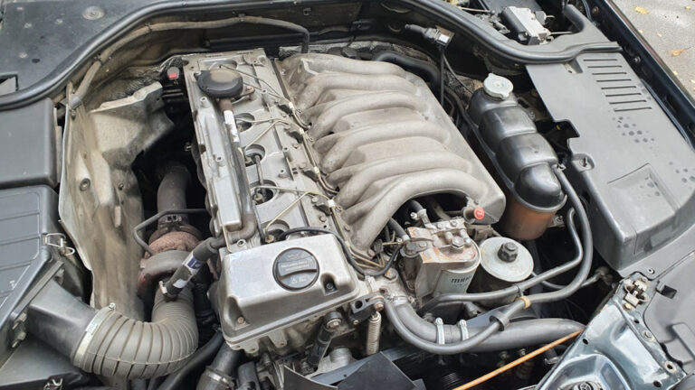
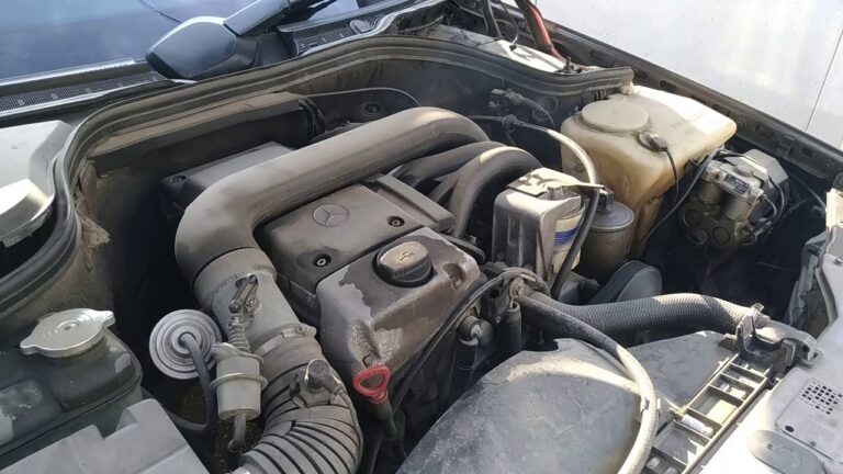
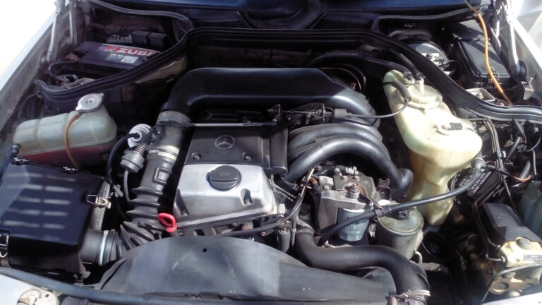
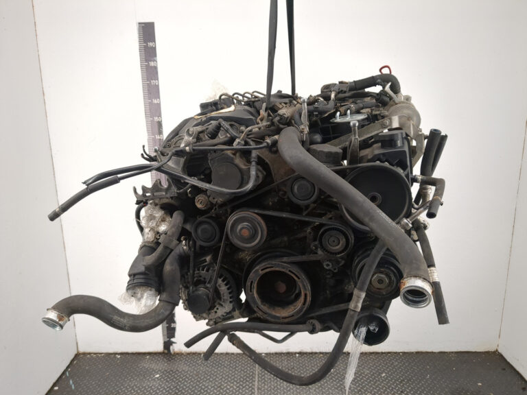
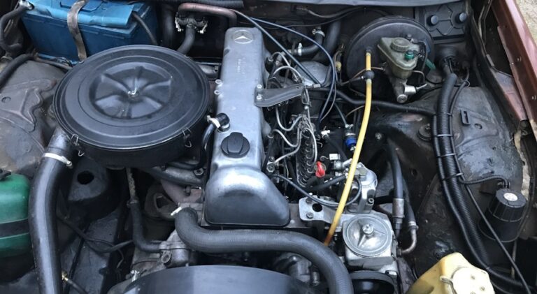
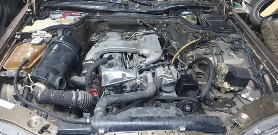
The Mercedes-Benz OM602 is a family of five-cylinder diesel engines used in passenger cars, G-Class models and commercial vehicles. It includes 2.5-liter and 2.9-liter versions, naturally aspirated and turbocharged configurations, and two substantially different fuel-injection architectures. The full 602.xxx engine number—not simply the OM602 family designation—is needed to identify the correct specification and repair procedure.
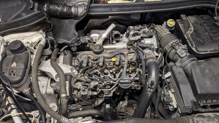
Earlier OM602 engines use prechamber indirect injection with an inline injection pump. Selected turbocharged versions add electronic diesel-system controls while retaining that basic fuel-injection arrangement. Later 2.9-liter DE29LA engines employ direct injection and electronically controlled Bosch distributor-type injection pumps; they are not common-rail diesels.
Mercedes service literature identifies specific conditions involving timing-chain elongation in certain W124 production batches, damage to the piston-type vacuum-pump drive, cylinder-head oil leakage, and noise associated with oil-filter housing seals. Fuel-system leaks and other symptoms also appear in owner and technician accounts. Their diagnosis depends on the particular engine version, rather than on an assumed OM602-wide failure pattern.
Mercedes-Benz OM602
OM602 Specifications and Engine Codes
The 2.5-liter OM602 has an 87.0 mm bore and 84.0 mm stroke, producing 2,497 cc. The larger 2.9-liter versions use an 89.0 mm bore and 92.4 mm stroke for 2,874 cc. Both are five-cylinder, two-valve-per-cylinder designs with an aluminum-alloy cylinder head and chain-driven overhead camshaft. Their combustion systems and component configurations are not necessarily interchangeable.
| Specification | OM602 2.5 | OM602 2.9 |
|---|---|---|
| Displacement | 2,497 cc | 2,874 cc |
| Bore × stroke | 87.0 × 84.0 mm | 89.0 × 92.4 mm |
| Cylinder arrangement | Inline-five | Inline-five |
| Block / head | Cast iron / aluminum alloy | Cast iron / aluminum alloy |
| Valve layout | SOHC, 10 valves | SOHC, 10 valves |
| Camshaft drive | Chain, duplex roller type in documented versions | Chain, duplex roller type in documented versions |
| Injection | Prechamber, inline pump | Prechamber with inline pump (D29) or direct injection with distributor pump (DE29LA) |
| Induction | Naturally aspirated or turbocharged | Naturally aspirated D29 or turbocharged DE29LA |
Factory Output by Version
Power, torque and compression ratio must be tied to a specific variant and application. Two values from separate markets should not be combined into an invented engine-wide output range.
| Engine Code | Documented Configuration | Power | Torque | Compression |
|---|---|---|---|---|
| 602.911 | 190 D 2.5, early European W201 | 66 kW / 90 PS | 154 Nm | 22.0:1 in documented specification |
| 602.911 | 190 D 2.5, U.S. specification described in MBNA literature | 69 kW | 165 Nm | 22.0:1 |
| 602.912 | 250 D, early European W124 | 66 kW / 90 PS | 154 Nm | Check exact application |
| 602.961 | 190 D 2.5 Turbo, European W201 | 90 kW / 122 PS | 225 Nm | 22.0:1 |
| 602.961 | 190 D 2.5 Turbo, U.S. Federal specification | 92 kW | 228 Nm | 22.0:1 |
| 602.962 | 300 D 2.5 Turbo, U.S. Federal W124 | 90 kW | 223 Nm | Check exact specification |
| 602.942 | 290 GD, W461 | 70 kW / 95 PS | 192 Nm | 22.0:1 |
| 602.980 | Sprinter 310 D, Bosch catalogue entry | 75 kW | Not established in cited entry | Not established in cited entry |
| 602.980 | Sprinter 312 D, Bosch catalogue entry | 90 kW | Not established in cited entry | Not established in cited entry |
| 602.982 | E 290 Turbodiesel, W210 | 95 kW / 129 PS | 300 Nm | 19.5:1 |
| 602.983 | G 290 TD, W461 | 88 kW / 120 PS (Mercedes) | 280 Nm in technical catalogues | Not established here |
For the European 602.961, Mercedes specifies 90 kW at 4,600 rpm and 225 Nm at 2,400 rpm. For the 602.982, Mercedes specifies 95 kW at 4,000 rpm and 300 Nm between 1,800 and 2,400 rpm. The latter is a direct-injection engine despite sharing the OM602 name with the prechamber models.
The Bosch diesel catalogue independently identifies 602.980 in the 75 kW Sprinter 310 D (January 1997–March 2000 listing) and the 90 kW Sprinter 312 D (February 1995–March 2000 listing). It also separates injection-pump entries by engine-number breakpoints and configuration codes. These are catalogue application periods, not a complete record of engine manufacturing dates.
Mercedes Vehicles Using the OM602
The family was installed in W201 and W124 passenger cars, later W210 models, G-Class vehicles, and commercial applications. Badge alone is unreliable: a 2.9-liter OM602 may use either prechamber or direct injection depending on the engine suffix.
| Model | Chassis / Type | Engine | Documented Scope |
|---|---|---|---|
| 190 D 2.5 | W201 / 201.126 | 602.911 | European and North American versions; outputs and years differ |
| 190 D 2.5 Turbo | W201 / 201.128 | 602.961 | European archive series beginning February 1986 and ending August 1988; separate market specifications exist |
| 250 D | W124 / 124.125 | 602.912 | European applications beginning in 1985 |
| 300 D 2.5 Turbo | W124 / 124.128 | 602.962 | U.S. model years 1990–1993 in the referenced service material |
| 290 GD | W461 / 461.337 | 602.942 | Short-wheelbase factory series, 1992–1997 |
| Sprinter 310 D | W901–905 family; exact type varies | 602.980 | 75 kW direct-injection application identified by Bosch |
| Sprinter 312 D | W901–905 family; exact type varies | 602.980 | 90 kW direct-injection application identified by Bosch |
| E 290 Turbodiesel | W210 / 210.017 | 602.982 | Mercedes archive: March 1996–June 1999 main series |
| E 290 Turbodiesel T-Modell | S210 | 602.982 | Documented estate application |
| G 290 TD | W461 | 602.983 | Turbocharged direct-injection version announced September 1997 |
Additional 602.940, 602.946 and other 2.9-liter applications appear in the T1, Sprinter, Vario and G-Class ranges. These require separate engine-number and market verification; a generic OM602 family listing does not establish precise fitment for each vehicle year or body type.
Mechanical Design and Fuel-System Differences
Bottom End and Pistons
The OM602 has a cast-iron block and aluminum-alloy cylinder head. Mercedes’ service manual for documented 602.91/96 engines describes six main-bearing positions, crankshaft and bearing inspection, piston and ring servicing, and cylinder repair procedures. The existence of these procedures does not demonstrate a characteristic rate of crankshaft, bearing or cylinder failure.
A documented revision replaced lead-coated piston skirts with graphite-treated skirts on certain 602.91 engines. Mercedes service information 01/22b identifies the revised piston as 601 030 22 17 and permits its installation in older applicable engines. The revision is relevant to parts identification; by itself it does not prove that the earlier piston was defective.
Mercedes also distinguishes piston oil-cooling jet arrangements between certain naturally aspirated and turbocharged 2.5-liter engines. During a rebuild, the jet arrangement and its direction must match the actual version. Components identified for 602.96 should not be transferred automatically to 602.91 or the later DE29LA engines.
Cylinder Head and Valvetrain
The single overhead camshaft operates ten valves. The 2.5-liter engines covered by the MBNA service manual use hydraulic valve-lash compensation, so periodic manual valve-clearance setting is not a routine service requirement for those versions.
Mercedes revised the hydraulic elements in September 1987 by adding a 0.2 mm ventilation opening, intended to reduce noise associated with short trips. A January 1990 revision changed internal dimensions and the oil reservoir to encourage quicker filling after startup. The changes are useful when identifying components or investigating a startup ticking complaint, but do not establish a failure rate for earlier tappets.
Timing Chain and Oil-Pump Drive
The overhead camshaft is driven by a roller chain; Mercedes factory information specifies a duplex chain for the 190 D 2.5 Turbo, 290 GD and E 290 Turbodiesel applications. In documented 2.5-liter engines the oil pump has a separate chain drive. These are different components, and supplier changes recorded for one chain must not be assigned to the other.
Correct mechanical timing depends on the relationship between crankshaft, camshaft and injection-pump drive. Engine-specific procedures are required after work on the timing drive, particularly where sprockets, chain links or injection-pump timing components have been disturbed.
Prechamber Injection and Later Bosch Direct Injection
| Feature | Prechamber D25 / D29 | Direct-Injection DE29LA |
|---|---|---|
| Combustion | Indirect injection through prechambers | Direct injection |
| Injection pump | Five-element inline pump | Electronically managed Bosch distributor pump |
| Control | Mechanical governing, plus EDS functions on selected turbo engines | Electronic diesel management |
| Induction | Atmospheric or turbocharged depending on suffix | Turbocharged, with charge-air cooling in documented applications |
| Examples | 602.911, 602.912, 602.942, 602.962 | 602.980, 602.982, 602.983 |
The naturally aspirated 602.942 in the 290 GD uses prechamber injection with a 22.0:1 compression ratio. The 602.982 in the E 290 Turbodiesel uses 19.5:1 compression, Bosch direct injection, a turbocharger and intercooler. The shared 2.9-liter displacement does not imply shared injection components or diagnostic procedures.
The U.S. 602.962 retains its prechamber/inline-pump architecture, while an electronic diesel system (EDS) manages functions including idle speed, EGR and boost control. Mercedes’ 1992 model-year introduction describes changes to prechamber volume, injection-pump cam profile, vacuum layout and EDS control equipment. These are application-specific changes—not a switch to the direct-injection Bosch distributor system.
Lubrication, Cooling and Emissions Hardware
The documented 2.5-liter engine uses a gear-type oil pump, oil filtration, a water pump and thermostat. Oil-cooler equipment, sump design, piston-cooling provisions and total fluid capacities differ by installation. The 602.962’s EDS controls EGR and boost-related functions; the later E 290 Turbodiesel uses its own Bosch electronic management and a factory-listed oxidation catalyst. There is no basis for assigning the same emissions hardware or electronic fault-code definitions to every OM602.
Timing-Chain Elongation: The Restricted W124 Bulletin
Mercedes-Benz service information 05/93, dated November 1995, describes engine-running complaints caused by a stretched timing chain in specified W124 vehicles with OM602/OM606 engines and W140 vehicles with OM603 engines. The cited production period is July 1992 to April 1994, subject to the bulletin’s individual chassis ranges.
| W124 Chassis End Number | From | To |
|---|---|---|
| B | B810470 | B999999 |
| C | C000001 | C142875 |
| J | J001335 | J049633 |
| F | F231885 | F293159 |
Listed complaints include chain-area noise, rough running, hard starting, loss of power and increased oil consumption. None proves chain elongation in isolation. Mercedes instructs technicians to establish basic camshaft timing by aligning the camshaft reference marks and reading the resulting crankshaft position.
Timing Deviation in Service Information 05/93
The bulletin instructs inspection of the camshaft sprocket after turning the engine two full revolutions in the normal direction. Where tooth damage is present, the repair extends beyond a replacement chain. Where timing deviation exceeds 10°, the engine must be assessed for possible piston-to-valve contact before the timing repair is considered complete.
These thresholds belong to the specified bulletin procedure; they are not an OM602-wide maintenance interval or a universal timing-chain wear limit. The bulletin is also not a safety recall for every OM602-powered vehicle.
Vacuum-Pump Damage and Secondary Timing-Drive Repairs
Mercedes-Benz service information 43/9, February 1991, addresses roller and bearing damage in the piston-type vacuum pump used on applicable 601, 602 and 603 installations. Where the pump drive roller or bearing is damaged, Mercedes directs inspection of the cam that operates the pump on the injection-timing device. Damaged interacting components must not be overlooked during pump replacement.
The upstream fault is the roller/bearing or associated drive damage. Additional damage in the chain-drive area is a possible consequence, not the starting diagnosis in every case.
Technician field report: A detailed 2012–2013 PeachParts repair thread involving a 1992 300D 2.5 Turbo describes vacuum-pump bearing components entering the timing-drive area, damage to the chain and subsequent extensive engine work. The thread includes physical inspection findings; it does not establish a percentage of OM602 engines affected or a predictable failure mileage.
If a pump is removed after mechanical damage, inspecting the pump alone may be insufficient. The relevant drive cam, adjacent timing components and any suspected debris-related damage need assessment before a replacement pump is put into service. The correct repair scope depends on what has actually failed.
Cylinder-Head Oil Leaks and Oil in Coolant
External Oil Leakage at the Head Joint
Mercedes service information 01-85101 addresses oil leakage between the cylinder head and head gasket where an oil-return passage is insufficiently sealed. A revised gasket introduced a metallic sealing feature around the passage for documented applications.
This is not necessarily combustion-gas leakage. Oil that starts at the head joint may spread across nearby engine surfaces, making its final visible location a poor guide to the actual origin. Before cylinder-head removal, the initial leak point should be located and nearby external sources excluded.
Owner reports: Some 300D 2.5 Turbo discussions describe oil around the front or side of the head, including complaints following earlier gasket work. Their observations do not prove the precise factory mechanism in each case.
Oil Entering the Cooling System
Service information 01-87101 describes a separate condition: oil entering coolant because of porosity in a cylinder-head casting in covered 601/602/603 applications. Contaminated coolant alone does not identify whether the cause is head porosity, another internal communication path or an unrelated problem.
Where the casting defect specified by Mercedes is confirmed, the relevant repair involves replacement of the defective head and cleaning the contaminated cooling system. Replacing an external oil-return gasket does not remedy a porous casting. Neither condition can be treated as a proven defect of every OM602 head or every 2.9-liter version.
Hydraulic Tappet Noise and Oil-Filter Housing Seals
Mercedes service information 18/11a, revised June 1991, instructs checks of two O-rings on the stem of the oil-filter housing lid on engines 602 and 603. Damaged or hardened rings can allow oil in the filter housing to drain into the sump after shutdown, affecting oil availability when the engine is restarted.
The bulletin is particularly relevant to a noisy engine during or after starting, especially when hot. Mercedes specifically recommends inspecting these rings before replacing hydraulic valve tappets. If one is damaged, both are to be replaced. The bulletin also observes that a momentary ticking sound immediately after startup may be normal.
For the documented application, the O-ring part number is 015 997 94 48. Current fitment must be verified against the specific filter-housing design.
The diagnostic sequence matters: a tappet-like noise is not proof of a failed tappet. Oil retention in the filter assembly should be addressed before undertaking more extensive valvetrain work; persistent or progressive noise still requires diagnosis.
Fuel-System Leaks: Three Different Fault Paths
Inline-Pump Delivery-Valve Seals
Owners of 300D 2.5 Turbo cars report diesel appearing around the delivery-valve holders of the inline injection pump. In one account, leakage returned about 500 miles after seals and copper washers had been replaced. The exact reason for that recurrence was not independently established.
A wet delivery-valve holder does not itself prove a defective pumping element or justify replacing the entire pump. The exact leak location, parts fitted and outcome of any earlier seal work need to be established before further repairs.
High-Pressure Injection Pipes and Vibration
Mercedes bulletin 07.1-89011, January 1989, specifically addresses fuel leakage from injection pipes serving cylinders 1–4 on covered 601, 602 and 603 engines due to vibration. Its remedy calls for double-cone-type injection lines and correct installation of the plastic retaining clips.
Thus, a diesel leak near the pump or injectors can originate in the high-pressure line or its connections rather than inside the injection pump. A pipe replacement without the proper clips and routing may leave the vibration issue unresolved. The bulletin’s listed replacement part numbers must be checked against the exact installation; its existence does not establish a fleet-wide rate of failure.
Bosch Distributor-Pump Seals on DE29LA Engines
The Bosch distributor pump fitted to 602.980, 602.982 and related DE29LA applications is different from the prechamber engines’ inline pump. Sealing work can involve components whose adjustment or electronic operation matters after reassembly.
Owner reports: A 1998 E 290 Turbodiesel owner described an engine that started after distributor-pump seal replacement but no longer responded properly to the accelerator. Separately, a G 290 TD owner reported cold-weather fuel leakage at 223,000 km, without a fully confirmed failed component or documented successful repair. Neither account establishes a universal Bosch-pump defect or a verified failure-mileage threshold.
Diagnosis should separate an external leak from electronic-control, post-repair adjustment and internal fuel-delivery problems. An inline-pump delivery-valve repair procedure must not be transferred to the distributor pump.
Turbocharging, EGR and EDS Fault Diagnosis
The U.S. 602.962 retains prechamber injection but adds electronic control of idle speed, EGR and boost-related functions. A loss of power therefore need not be caused by a mechanically damaged turbocharger. Airflow sensing, pressure measurement, vacuum routing and actuators are distinct areas of the factory diagnostic system.
Mercedes updated the EDS hardware and vacuum arrangement across model years. In the earlier 602.962 control layout, separate vacuum transducers Y31/2 and Y31/3 are identified for the intake pressure-control flap and wastegate functions. In the documented U.S. 1992 layout, combined transducer Y31/5 is used with the relevant switchover valves. The correct wiring and vacuum diagram must be selected by model year before interpreting a diagnostic code.
1992 U.S. 300 D 2.5 Turbo EDS Impulse Codes
The following table describes the 1992 602.962 strategy documented in the Mercedes model-year introduction. The impulse-counter diagnostic connection is X11/4, contact 4. Code definitions identify a component or control circuit for testing, not a confirmed mechanical root cause.
| Code | Factory Diagnostic Area — 1992 U.S. 602.962 |
|---|---|
| 1 | No stored malfunction |
| 2 | Fuel rack position sensor L7 |
| 3 | Airflow sensor B2/1 |
| 4 | EDS control unit N39 / atmospheric-pressure sensor |
| 5 | EGR vacuum transducer Y31/1 or EGR control circuit |
| 6 | EDS internal voltage supply |
| 7 | Starter ring-gear speed sensor L3 |
| 8 | Coolant-temperature sensor B11/4 |
| 9 | Intake-air-temperature sensor B2/1a |
| 10 | Voltage supply |
| 11 | Electronic idle-speed (ELR) actuator or EGR vacuum transducer Y31/1; indicated for the documented short-circuit condition |
| 12 | Not used |
| 13 | EDS control unit N39 internal memory |
| 14 | EDS pressure sensor B5/1 |
| 15 | Combined boost-pressure/pressure-control-flap vacuum transducer Y31/5 or associated boost-control circuit |
For this 1992 version, code 11 should not automatically be described as a failed boost cut-out valve; the documented row identifies the ELR actuator or EGR transducer circuit. Likewise, code 15 refers to the 1992 Y31/5 configuration, while the earlier Y31/2/Y31/3 descriptions belong to other versions. Some earlier tables also assign code 10 differently. Combining those tables without the model-year distinction can misdirect repairs.
Mercedes’ earlier diagnostic documentation additionally notes special readout conditions for certain EGR-related faults. A stored code should be followed by the applicable component and control-circuit tests. For a vehicle with a loss-of-power complaint but no stored EDS fault, the factory material still directs functional checks of idle-speed control, EGR and boost-related operation where relevant.
The direct-injection 602.980/602.982/602.983 engines use different electronic management and must not be diagnosed from the preceding table. Oil found in a turbo inlet or boost pipe is also not, by itself, confirmation of turbocharger-bearing, turbo-seal or piston-ring failure.
Production Revisions and Repair Compatibility
Mercedes made changes to the 2.5-liter engines during production. Some affected operating characteristics; others concern fastener strength, replacement-component compatibility or manufacturing revisions. A revised part does not automatically mean the original had a statistically frequent failure.
| System | Change | Documented Timing / Scope | Repair Significance |
|---|---|---|---|
| Hydraulic tappets | Approximately 0.2 mm vent opening | September 1987 | Short-trip tappet noise behavior |
| Hydraulic tappets | Revised internal geometry and reservoir | January 1990 | Improved filling after startup |
| Camshaft sprocket fastener | M10 to M11 stretch-type design | November 1988, applicable engines | Hardware and tightening procedure |
| Oil-pump drive chain | Open-sleeve chain construction | June 1988, documented 602/603 applications | Change intended to reduce wear |
| Camshaft timing chain | Iwis chain with increased-clearance sleeves | February 1989, with engine-number applicability | Component identification |
| Camshaft timing chain | Daido chain use resumes | September 1989, applicable production | Timing-chain supplier revision, not an oil-pump-chain change |
| Head gasket | Revised oil-return sealing | April 1987, covered applications | Relevant to external oil leakage |
| Cylinder-head bolts | Increased tensile strength | 602.96 from May 1990; 602.91 from June 1991 | Replacement fasteners and tightening procedure |
| Piston skirts | Graphite-treated surface replaces lead coating | 602.91; exact production breakpoint not established | Replacement piston identification |
| Prechamber / injection pump | Increased prechamber volume and pump-cam change | 602.962 U.S., model year 1992 | Do not transfer to 2.9 DE29LA |
Mercedes bulletin 01/22b identifies higher-strength bolts on turbocharged 602.96 engines and later naturally aspirated 602.91 versions. The revised turbo-engine bolts have different head markings (95 or 950 rather than 85 or 850) and identifying ribs. When the head is removed on an applicable 602.96 engine, Mercedes directs that the earlier bolts be replaced with the modified type; reused bolts must also satisfy the factory maximum-length criteria and tightening instructions.
Mercedes service-manual section 05-320 distinguishes the 1989 Iwis and Daido camshaft timing-chain changes. It does not support attributing that supplier change to the oil-pump chain. Exact engine-number breakpoints should be checked when ordering timing components.
Maintenance, Fluids and Mechanical Checks
Oil Changes and Fill Quantities
Mercedes-Benz North America service information 00/44 from October 1991 specifies that the lubrication-service interval for the U.S. 300 D 2.5 Turbo (124.128) remains 5,000 miles (approximately 8,000 km). The bulletin contrasts that figure with a 7,500-mile interval for the different 300 SD (140.134); the latter must not be assigned to the 124.128.
| Specific Application | Service Item | Published Value |
|---|---|---|
| 300 D 2.5 Turbo, 124.128, U.S. | Lubrication service | 5,000 miles / approximately 8,000 km (MBNA 00/44) |
| 300 D 2.5 Turbo, 1990 U.S. owner’s manual | Oil with filter | Approximately 7.5 L in that manual; later service revisions must be considered |
| 290 GD, 461.337 / 602.942 | Oil with filter | 7.0 L |
| 290 GD, 461.337 / 602.942 | Coolant including heater | 7.35 L |
A later Mercedes oil-capacity bulletin calls for a 0.5 L reduction on specified covered applications. That instruction cannot safely be applied by subtracting 0.5 L from any unrelated published capacity. Sump, oil cooler, filter assembly and model-year revisions must be checked against the actual vehicle.
For U.S. 124.128 coolant capacity, a 1990 owner’s manual gives approximately 9.5 L, whereas an engine service-manual table gives 9.0 L. The differing document editions and measurement basis have not been fully reconciled; either value would be misleading if presented as the entire OM602 family’s capacity.
Engine-oil approval, viscosity, coolant specification, fuel-filter intervals and severe-duty schedules must be selected from the appropriate vehicle and market documentation. No single universal oil or coolant capacity, oil approval or service interval is established for all OM602 versions.
Timing-Chain and Valve Service
The OM602 uses a timing chain rather than a scheduled timing belt. No one replacement-mileage interval can be verified for every OM602 engine. For vehicles within the scope of service information 05/93, mechanical timing checks and any resulting chain or sprocket work should follow that bulletin. Other variants require their own service limits.
The applicable 2.5-liter hydraulic valvetrain does not require routine mechanical valve-lash setting. Persistent startup noise should be assessed together with oil-filter housing seal condition before replacing hydraulic elements. Where compression testing is required, the MBNA service manual gives approximately 80°C test temperature and, for the covered 602.91/96 engines, 26–32 bar normal compression, about 18 bar minimum and 3 bar maximum cylinder-to-cylinder difference. These figures are not specifications for every later 2.9-liter version.
Symptoms and Diagnostic Pitfalls
| Complaint | Systems to Distinguish | Supported Next Check |
|---|---|---|
| Noise near chain drive | Camshaft chain, pump drive, adjacent components | Mechanical timing and applicable vacuum-pump-drive inspection |
| Ticking immediately after startup | Hydraulic tappets, oil drain-back at filter housing | Duration, oil-filter stem O-rings and relevant tappet tests |
| Hard cold starting | Glow system, fuel delivery, injection, compression | Check relevant system before diagnosing internal engine damage |
| Rough running or loss of power | Timing, fuel delivery, EGR, EDS/boost control | Verify timing or version-specific electronic tests as symptoms warrant |
| Oil at cylinder-head joint | Head-gasket oil-return passage, other nearby leakage | Identify the earliest visible source of oil |
| Oil in coolant | Cylinder-head porosity or another internal fluid path | Establish the physical source before selecting repair |
| Diesel at injection equipment | Inline pump holder seals, distributor-pump body, high-pressure pipes | Identify pump architecture and exact leaking component |
| Low turbocharged-engine power | Pressure/airflow sensing, vacuum transducers, EGR, turbo hardware | Use the applicable EDS or EDC strategy, not generic turbo assumptions |
| Engine continues running with key off | Vacuum-operated shutoff and related controls on applicable versions | Inspect the actual shutoff circuit before assuming injection-pump damage |
Additional owner observations: A W201 diesel owner reported difficult cold starting and unstable running, while another owner described a 250 D that did not stop when the ignition was switched off. Neither account established a confirmed OM602-wide fault. They are useful because the complaints point to distinct diagnostic paths rather than the same injection-pump diagnosis.
An isolated 1992 300D 2.5 Turbo owner report described approximately 302,000 miles of accumulated use and oil consumption of about one U.S. quart per 3,000 miles. It is not an official permissible oil-consumption specification and cannot establish ring wear, turbocharger condition or average engine lifespan without mechanical examination.
Factory Service Bulletins and Recall Status
| Document | Subject | Applicable Technical Point |
|---|---|---|
| 01-85101 | Oil leakage at head/gasket joint | Revised oil-return sealing |
| 01-87101 | Oil in cooling system | Documented cylinder-head porosity condition |
| 07.1-89011 | Injection pipes leaking under vibration | Double-cone pipes and correct retaining clips, cylinders 1–4 |
| 43/9 | Piston-type vacuum-pump repair | Check associated drive cam after bearing/roller damage |
| 18/11a | Oil-filter stem O-rings | Check oil drain-back condition before tappet replacement |
| 00/44 | Lubrication-service intervals | 124.128 at 5,000 miles; distinguish from 140.134 |
| 01/22b | Head bolts and pistons | Revised fasteners, torque procedure and piston coating |
| 05/93 | Chain elongation in restricted production batches | Timing deviation, sprocket checks and possible valve contact |
| 58/92 | Timing-chain connecting link and tools | Correct replacement assembly procedure |
These are service-information documents, not automatically safety recalls. The material referenced here does not establish an engine-wide OM602 safety recall, warranty extension or defect percentage. A specific vehicle’s recall eligibility must be checked by VIN in the relevant market; a negative finding for one engine or jurisdiction does not prove absolute absence of all campaigns.
What to Inspect Before Buying an OM602 Vehicle
- Confirm the full engine code. Identify 602.xxx and the vehicle’s market/version before using technical data or ordering parts.
- Observe a cold start. Note extended cranking, unstable running and abnormal mechanical noise; do not diagnose solely from the symptom.
- Review timing-system records. For W124 applications, determine whether service information 05/93’s production and chassis restrictions apply.
- Inspect vacuum-pump service history. Evidence of pump-drive damage makes associated timing-component inspection especially important.
- Locate oil leaks precisely. Look for the initial source near the head joint or pump area, not just where oil collects.
- Examine the cooling system. Investigate oil contamination and unexplained coolant loss before selecting head or gasket repairs.
- Check fuel-system sealing. Differentiate inline-pump holders, high-pressure pipes and distributor-pump sealing points.
- Evaluate acceleration in turbocharged versions. Distinguish control-system faults from evidence of turbocharger mechanical damage.
- Check the appropriate electronic system. EDS definitions for a U.S. 602.962 do not apply automatically to DE29LA Bosch EDC.
- Review previous repairs and fluid specifications. Confirm revised components, correct procedures and vehicle-specific oil and coolant data.
OM602 Reliability in Practice
The OM602 designation encompasses engines with different displacement, injection hardware, control systems and service requirements. The 2.5-liter prechamber engines, the electronically assisted U.S. 300 D 2.5 Turbo, the naturally aspirated 290 GD and the direct-injection DE29LA engines should not be diagnosed as identical units.
Specific Mercedes documents support timing-chain checks for restricted W124 batches, vacuum-pump-drive inspection after roller or bearing failure, oil-leak diagnosis at the head joint, investigation of oil in coolant, and oil-filter O-ring checks before hydraulic tappet replacement. These are stronger claims than a generic list of supposed OM602 problems because their mechanisms and repair implications are identifiable.
Owner and technician reports add fuel leaks, cold-start complaints, oil consumption and examples of secondary damage. They remain useful evidence of what can happen in individual vehicles, not a reliable population failure rate. Neither a universal failure-mileage threshold nor an average OM602 lifespan can be established from these sources.
Sources & Technical References
- Mercedes-Benz Public Archive — 190 D 2.5 Turbo. Factory data for the European 602.961.
- Mercedes-Benz Public Archive — 290 GD. 602.942 output, architecture, compression and fluid capacities.
- Mercedes-Benz Public Archive — E 290 Turbodiesel. 602.982 direct injection, turbocharging and specifications.
- Mercedes-Benz Public Archive — G 290 TD introduction. Factory 88 kW G-Class information.
- Bosch — Diesel Catalogue. OM602.980 Sprinter 310 D/312 D output, periods and pump fitment; late-model applications.
- Mercedes-Benz of North America — Service Manual Engines 602, 603 (LZ S-2517-091). Mechanical design, service specifications and revisions; OEM documentation mirror.
- Mercedes-Benz — Introduction into Service, Model Year 1992. 602.962 control system, vacuum revision and model-year EDS impulse codes; OEM documentation mirror.
- Mercedes-Benz — Service Information 05/93. Timing-chain complaint, chassis limits, inspection and repair.
- Mercedes-Benz — Service Information 43/9. Vacuum-pump roller/bearing and drive-cam inspection.
- Mercedes-Benz — MBNA 18/11a. Oil-filter O-rings and tappet noise.
- Mercedes-Benz — Service Information 07.1-89011. Double-cone high-pressure pipes and plastic clips for cylinders 1–4.
- Mercedes-Benz — Service Information 01/22b. Revised 602.91/96 head bolts and graphite-treated pistons.
- Mercedes-Benz — MBNA 00/44. 124.128 lubrication-service interval; hosted under another model index but applicable text identifies the diesel.
- Mercedes-Benz — Service Information 01-85101. Oil-return passage and head-gasket external oil leak.
- Mercedes-Benz — Service Information 01-87101. Cylinder-head casting porosity and coolant contamination.
Field Sources
- PeachParts — 1992 300D 2.5 Vacuum Pump Failure. Physical repair observations and timing-drive damage.
- PeachParts — Delivery Valve Seals Leaking Again. Recurrent inline-pump seal leakage reported by an owner.
- MBWorld — E290TD 1998 Bosch Injection Pump. Owner-reported control problem following distributor-pump sealing work.
- Viermalvier — OM602 DE29LA Pump Leak. G 290 TD cold-weather fuel leakage at owner-reported 223,000 km.